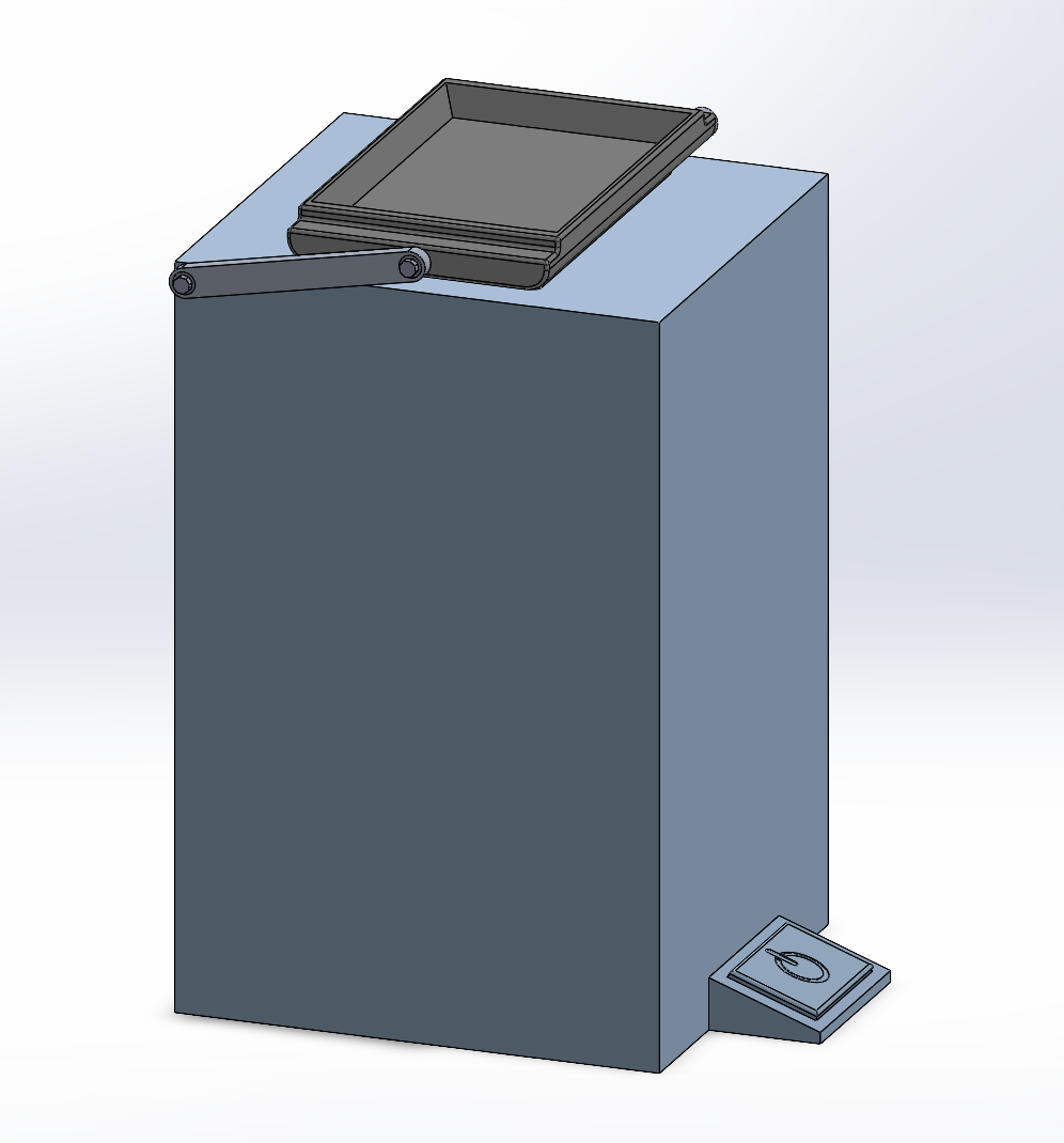
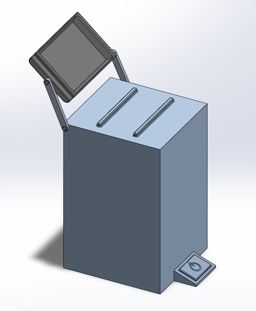
The goal of this project was to design a linkage mechanism to transport an object along a specified motion as part of a mechanical design class. For this project, I designed an automated trash can that transports trash placed on top of a trashcan into an opening in the back. The project required a 35cm wide tray that is centered on a 65cm wide trashcan, with an opening on the back 15cm from the top. The mechanism must not have any interference during motion.
Initial designs for the linkage were sketched in Math Illustrations by tracing the position of the tray at 3 points in its motion. From the ends of the tray, two perpendicular bisector lines were formed. The point of intersection of these lines suggested the locations where the crank and rocker arms connect to the trashcan. These locations also inform the length of the crank and rocker arms.
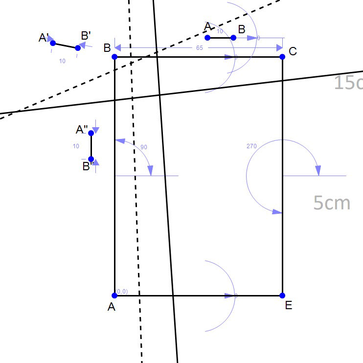
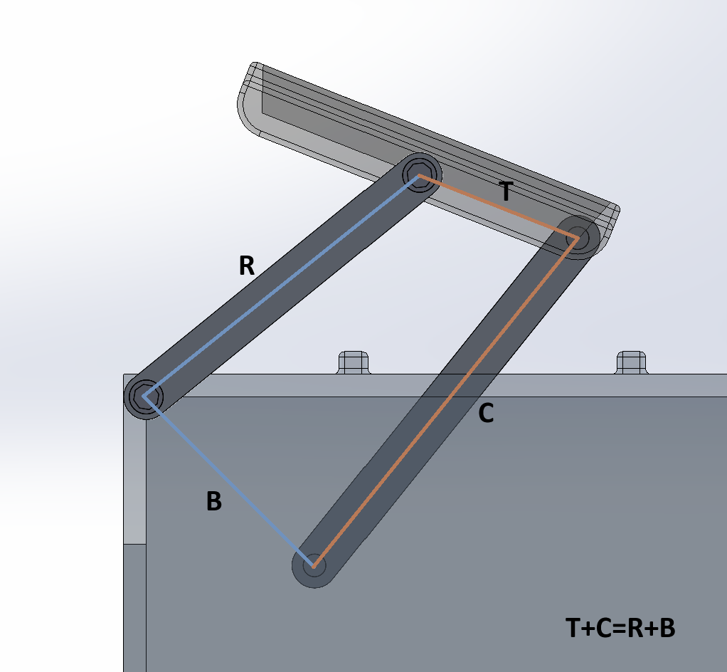
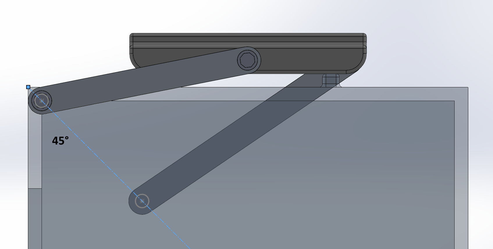
Working in Math Illustrator gave some basic relationships that allowed for ways to simplify the geometry between parts in this design. For example, the sum of the tray and crank length must equal the sum of the rocker and attachment point lengths. This allows the linkage arms to "flip" and keep the tray upright. Another essential geometry was that the points where the crank and rocker arms attach to the trashcan must be at a 45-degree angle in order for the tray to be perfectly horizontal at the top of the can and perfectly vertical at the opening in the back.
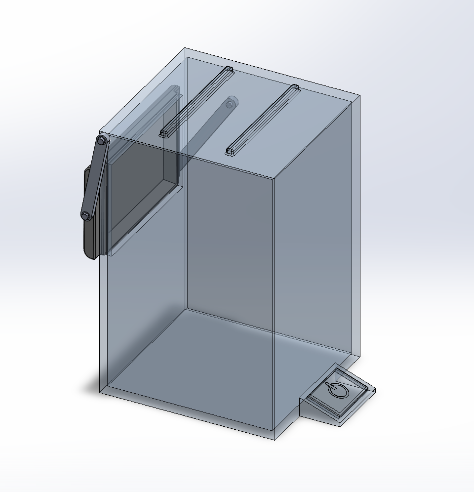
A preliminary design was drafted in SolidWorks. The crank rotates 336.6 degrees for the tray to move 90 degrees from horizontal to vertical. Future iterations could include an extrusion from the back of the trashcan to catch anything that falls off the tray while in motion. Experimenting with shorter linkage arms could help reduce the space needed for the trashcan to operate. SolidWorks motion analysis was used to demonstrate that within the constraints of the project, the mechanism follows the desired path of motion and meets design goals.